The raspberry pi 5 pinout shows a simple map of all the raspberry pi gpio pins. Each pin on the raspberry board has its own job. A diagram helps users pick the right pins for power, data, or special signals. Reading the raspberry pi pinout diagram with both physical and BCM numbers helps you wire things the right way. The raspberry pi pinout guide stops mistakes that could break pins or devices. With this guide, anyone can hook up sensors, lights, or other boards to raspberry pi gpio pins. The right pinout guide makes every raspberry project safer and works better. With the raspberry pi 5 pinout, users have a trusted chart for each pin on the raspberry board. This guide helps beginners and experts know what every raspberry pi pinout pin does. By following the raspberry pi pinout diagram, users make good choices for all raspberry gpio projects.
Key Takeaways
-
The Raspberry Pi 5 has a 40-pin header. Each pin has a job like power, ground, data, or special use. Knowing what each pin does helps you avoid mistakes and damage.
-
Always look at the pinout diagram. It shows both physical and BCM numbers. This helps you connect things the right way and keeps your board safe.
-
GPIO pins use 3.3V logic and can only handle a small amount of current. Never put 5V on these pins. Always use resistors with LEDs or switches to keep your Raspberry Pi safe.
-
The Raspberry Pi 5 can use I2C, SPI, and UART. These are special ways to talk to sensors and devices. You can connect many things for cool projects.
-
Start with easy projects like making an LED blink. This helps you learn how GPIO works. Then try harder projects using special features and new libraries for Raspberry Pi 5.
Raspberry Pi 5 Pinout Diagram
Pinout Table
The raspberry pi 5 pinout uses a 40-pin header. Each pin has a specific job. Some pins give power, some connect to ground, and others send or receive data. The raspberry pi pinout table below shows both the physical pin numbers and the BCM numbers. This helps users match the diagram to their code and wiring.
| Physical Pin | BCM GPIO Number | Function Description |
|---|---|---|
| 1 | N/A | 3.3V Power |
| 2 | N/A | 5V Power |
| 3 | GPIO 2 | I2C SDA (Data Line) |
| 4 | N/A | 5V Power |
| 5 | GPIO 3 | I2C SCL (Clock Line) |
| 6 | N/A | Ground (GND) |
| 7 | GPIO 4 | Digital I/O |
| 8 | GPIO 14 | UART TXD |
| 9 | N/A | Ground (GND) |
| 10 | GPIO 15 | UART RXD |
| 11 | GPIO 17 | Digital I/O |
| 12 | GPIO 18 | PWM |
| 13 | GPIO 27 | Digital I/O |
| 14 | N/A | Ground (GND) |
| 15 | GPIO 22 | Digital I/O |
| 16 | GPIO 23 | Digital I/O |
| 17 | N/A | 3.3V Power |
| 18 | GPIO 24 | Digital I/O |
| 19 | GPIO 10 | SPI MOSI |
| 20 | N/A | Ground (GND) |
| 21 | GPIO 9 | SPI MISO |
| 22 | GPIO 25 | Digital I/O |
| 23 | GPIO 11 | SPI SCLK |
| 24 | GPIO 8 | SPI CE0 |
| 25 | N/A | Ground (GND) |
| 26 | GPIO 7 | SPI CE1 |
| 27 | GPIO 0 | Digital I/O |
| 28 | GPIO 1 | Digital I/O |
| 29 | GPIO 5 | Digital I/O |
| 30 | N/A | Ground (GND) |
| 31 | GPIO 6 | Digital I/O |
| 32 | GPIO 12 | PWM |
| 33 | GPIO 13 | PWM |
| 34 | N/A | Ground (GND) |
| 35 | GPIO 19 | PWM |
| 36 | GPIO 16 | PWM |
| 37 | GPIO 26 | Digital I/O |
| 38 | GPIO 20 | Digital I/O |
| 39 | N/A | Ground (GND) |
| 40 | GPIO 21 | Digital I/O |
This table gives a quick way to check the raspberry pi pinout for any project. The raspberry pi gpio pinout diagrams often use both numbering systems. Users should always match the numbers in the diagram to the code they write.
Reading the Diagram
The raspberry pi 5 pinout diagram shows the 40-pin header as it appears on the board. Pin 1 sits at the top left when the board's USB ports face down. Odd-numbered pins run down the left side, and even-numbered pins run down the right. This layout helps users find the correct pins for their wires.
The raspberry pi pinout uses two numbering systems. Physical numbering counts the pins as they sit on the board. BCM numbering matches the Broadcom chip's internal names. Some projects use physical numbers, while others use BCM numbers. This difference matters because the same pin can have a different number in each system. For example, physical pin 3 is BCM GPIO 2. Users must check which system their code uses before connecting anything.
The raspberry pi gpio pinout diagrams help users avoid mistakes. They show which pins give power, which connect to ground, and which handle data. Power pins include 3.3V on pins 1 and 17, and 5V on pins 2 and 4. Ground pins appear at many spots, such as pins 6, 9, 14, 20, 25, 30, 34, and 39. Data pins support I2C, SPI, UART, PWM, and digital input or output. Each function appears in the diagram and table.
Tip: Always double-check the raspberry pi pinout before wiring. Using the wrong pin can damage the raspberry board or your devices.
Many users find interactive diagrams helpful. The RaspberryTips.com website offers a detailed and up-to-date guide. It shows the raspberry pi 5 pinout and explains each pin's job. Users can click on pins to see what they do. This makes learning the raspberry pi gpio pinout diagrams easier and safer.
The raspberry pi 5 pinout gives users a clear map for every project. By reading the diagram and table, anyone can connect sensors, lights, or other boards with confidence. The right diagram keeps projects safe and working well.
Raspberry Pi GPIO Pins Overview
Power and Ground Pins
The Raspberry Pi 5 has special pins for power and ground on its 40-pin header. These pins give steady power to sensors and other parts. The table below shows where each power and ground pin is and what voltage it gives:
| Pin Number | Function | Voltage Rating |
|---|---|---|
| 1 | 3.3V Power | 3.3V stable output |
| 17 | 3.3V Power | 3.3V stable output |
| 2 | 5V Power | 5V supply for peripherals |
| 4 | 5V Power | 5V supply for peripherals |
| 6 | Ground | 0V (Ground) |
| 9 | Ground | 0V (Ground) |
| 14 | Ground | 0V (Ground) |
| 20 | Ground | 0V (Ground) |
| 25 | Ground | 0V (Ground) |
| 30 | Ground | 0V (Ground) |
| 34 | Ground | 0V (Ground) |
| 39 | Ground | 0V (Ground) |
There are two 3.3V pins (Pin 1 and Pin 17) and two 5V pins (Pin 2 and Pin 4). Eight ground pins are spread out on the header. This setup lets you connect many things that need power or ground.
-
The GPIO pins use 3.3V logic. They cannot handle 5V. If you put more than 3.3V on a GPIO pin, it can break the board.
-
The 3.3V pins are good for small sensors.
-
The 5V pins can power bigger things like motors or USB devices.
-
All GPIO pins together should not use more than 50mA. Each pin can give or take between 2mA and 16mA. After reset, 8mA is the default.
-
For input pins, do not use more than 0.5mA.
Note: Always check what voltage and current your parts need before you connect them to the raspberry pi gpio pins.
Digital GPIO
The raspberry pi gpio pins have many general purpose input/output pins. These pins can be set as digital inputs or outputs. You can use them to read signals or control things.
-
Digital inputs and outputs let the Raspberry Pi 5 sense buttons or sensors and control LEDs or buzzers.
-
The board works with both raspberry pi digital inputs and raspberry pi digital outputs.
-
You can set each GPIO pin as an input or output in your code.
-
The general purpose input/output pins use 3.3V logic.
The raspberry pi gpios do not have a built-in analog-to-digital converter (ADC). This means it cannot read analog signals by itself. If you want to use analog sensors, you need to add an ADC chip or module.
Tip: When using gpio pins for digital inputs or outputs, always check the voltage so you do not break anything.
Communication Pins (I2C, SPI, UART)
The raspberry pi gpio pins can use different ways to talk to other devices. These ways are called protocols. The main ones are I2C, SPI, and UART.
| Protocol | Pins (GPIO Number) | Physical Pin Number | Function Description |
|---|---|---|---|
| I2C | GPIO 2 (SDA), GPIO 3 (SCL) | Pin 3 (SDA), Pin 5 (SCL) | Two-wire data and clock lines for i2c communication |
| SPI | GPIO 10 (MOSI), GPIO 9 (MISO), GPIO 11 (SCLK), GPIO 8 (CE0), GPIO 7 (CE1) | Pin 19 (MOSI), Pin 21 (MISO), Pin 23 (SCLK), Pin 24 (CE0), Pin 26 (CE1) | High-speed synchronous serial interface for peripherals |
| UART | GPIO 14 (TXD), GPIO 15 (RXD) | Pin 8 (TXD), Pin 10 (RXD) | Asynchronous serial communication (transmit and receive) |
-
The raspberry pi i2c pins (GPIO 2 and GPIO 3) let you use i2c with many sensors.
-
The raspberry pi spi pins (GPIO 10, 9, 11, 8, 7) help you send data fast to displays or memory chips.
-
UART uses GPIO 14 and GPIO 15 to send and get serial data.
These pins make the raspberry pi gpios great for connecting to lots of devices.
Special Functions and PWM
Some raspberry pi gpio pins have extra features. One important feature is Pulse Width Modulation (PWM). PWM lets the Raspberry Pi 5 change how bright an LED is or how fast a motor spins by turning the pin on and off very quickly.
-
Some pins can do hardware PWM, like GPIO 12, 13, 18, and 19.
-
PWM can make digital pins act like analog outputs.
-
Other special features are I2C, SPI, and UART, as shown above.
You can set up these special features in your code. Using gpio for PWM or communication lets you make cool projects.
Note: The Raspberry Pi 5 has a new GPIO control chip. The rpi.gpio library does not work on this board. People made the rpi-lgpio library to do the same things. This new library works differently inside. Some advanced things may need new libraries or special code.
The raspberry pi gpios give you many ways to connect and control things. If you use the gpio pins the right way, your projects will work well.
Safe Usage and Specs
Electrical Specs
The raspberry pi 5 gpio pins use 3.3V logic. Each gpio pin can handle up to 16 mA of current. All gpio pins together should not use more than 50 mA. Never put 5V on any gpio pin because it can break the board. The table below shows the main limits for the raspberry pi 5 gpio pins:
| Parameter | Value/Limit |
|---|---|
| GPIO Logic Voltage Level | 3.3 V |
| Maximum Current per GPIO Pin | 16 mA |
| Total Maximum Current (All Pins) | 50-51 mA |
| Voltage to Avoid on GPIO Pins | 5 V |
Always use resistors to limit current when you connect LEDs or other parts to the gpio pins.
Safe Wiring Tips
Wiring safely keeps your raspberry pi and devices working well. Follow these tips to stay safe:
-
Never put more than 3.3V on any gpio pin.
-
Always use resistors (220Ω–1kΩ) with LEDs or switches.
-
Do not plug or unplug wires while the raspberry pi is on.
-
Use outside power for motors or relays, not the gpio pins.
-
Touch the raspberry pi carefully to avoid static electricity.
Powering the raspberry pi through the gpio pins skips built-in safety and should not be done.
Common Mistakes
Many people make mistakes with raspberry pi gpio pins. Here are some common errors:
-
Using power supplies that are not official or do not fit the raspberry pi.
-
Connecting things that use too much current from the gpio pins.
-
Mixing up pin numbers, which can cause wiring mistakes.
-
Powering big devices like relays straight from the gpio pins.
-
Ignoring error messages or using old gpio libraries in code.
Always look at the pinout diagram and use official power supplies for the raspberry pi.
Expansion Boards and HATs
Expansion boards and HATs give the raspberry pi 5 new features. These boards plug into the gpio pins and help with bigger projects. Some popular choices are:
| Expansion Board / HAT | Features Added | Compatibility |
|---|---|---|
| IO Expansion Hat (DFRobot) | Pinout info, anti-reverse sockets | Raspberry Pi 5, 4, 3 |
| PCIe To 4-Ch M.2 Adapter Board | NVMe SSD support | Raspberry Pi 5 |
| Official Raspberry Pi AI HAT+ | AI acceleration (Hailo-8) | Raspberry Pi 5 |
| Industrial 6-Channel Relay Module | Relay control, isolation protection | Raspberry Pi 5 |
These boards let you add storage, wireless, or control motors and relays. Always check that the board works with the raspberry pi 5 and plugs into the right gpio pins.
Raspberry Pi Pinout Projects
Beginner Projects
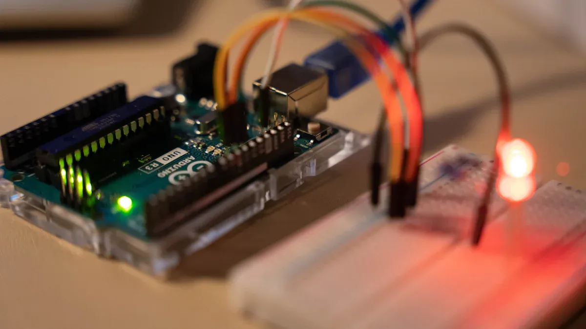
A lot of beginners start with easy raspberry pi gpios projects. These projects help people learn about gpio pins, inputs, and outputs. One popular raspberry pi gpio tutorial teaches how to use Python with the gpio pins. The guide explains how to set up the Python IDE. It also shows how to control gpio pins and write code. You can make an LED turn on or off when you press a button. This simple project helps you see the difference between inputs and outputs. It also teaches how to use the pins safely.
The table below lists some easy projects for beginners that use raspberry pi gpios:
| Project Name | Description | Key Components / Tools | Additional Resources / Guides |
|---|---|---|---|
| RGB Lights Setup | Control RGB WS2812B LED strips using raspberry pi gpios. | RGB WS2812B LED strips, USB 3.0 Hub | Step-by-step guide, beginner YouTube tutorial |
| Knight Rider Voice-Interactive Device | ChatGPT-enabled KITT replica using gpio pins for control. | Raspberry Pi 5, speaker, microphone | Video tutorials on "Knight Rider Historian" channel |
Most beginner projects cost under $75 if you already have a raspberry pi. Things like camera modules and cases do not cost much. The raspberry pi gpio tutorial community has lots of guides and videos. These make it easy to finish your projects fast.
Tip: Try simple programming first, like blinking an LED or reading a button, before you try harder raspberry pi gpios projects.
Advanced Projects
People with more experience can make bigger projects using raspberry pi gpios. One example is a smart home system. This project uses MOSFETs, transistors, voltage regulators, and shift registers. These parts help control many devices. Sensors like the DHT22 and HC-SR04 connect to the pins. They measure things like temperature, humidity, and distance. The raspberry pi gpios handle these inputs and outputs with careful code.
The Raspberry Pi 5 can be used for robotics, automation, and computer vision. Its better gpio header and extra camera ports help with hard tasks. You can control two 4K screens and use new wireless features. With advanced programming, you can build robots, smart mirrors, or gardens that water themselves.
Some problems in advanced projects are power needs, not enough pins, and keeping circuits safe. People fix these by using outside power, learning about each pin, and adding resistors or diodes. Careful wiring and checking your work help stop mistakes. Good programming, like using GPIO.cleanup(), keeps the pins safe after your code runs.
Tools and Resources
Many tools and libraries help with programming and hardware control. The rpi-lgpio library is new for Raspberry Pi 5. It replaces the old rpi.gpio library. This new library works in a way that feels familiar to people who used older guides. You should update your Raspberry Pi OS to make sure everything works right.
Here are some good libraries for raspberry pi gpios:
-
GPIO Zero: This Python library is easy for beginners.
-
RPi.GPIO: This is the original Python library and comes with the system.
-
pigpio: This library lets you use advanced gpio features and remote control.
-
PiCamera and PiCamera2: These are good for camera projects.
Online guides and tutorials show every step, from wiring to programming. The raspberry pi gpio tutorial community shares code, datasheets, and tips for fixing problems. These resources help you get better at programming with the raspberry pi gpio pins and avoid mistakes.
Note: Always make sure the libraries and guides you use work with Raspberry Pi 5 before you start a new project.
Knowing the Raspberry Pi 5 pinout helps people connect things safely. It lets you make fun and smart projects. You should look at pinout diagrams before you start. It is important to know what voltage each pin uses. Debugging tools can help you fix problems if something does not work. If you are new, start by giving power to the board the right way. Try hooking up easy parts, like an LED. You can use a gpio pin to make the LED blink. When you learn more about the pinout, you can make bigger projects. You will be able to control lots of devices. You can also use cool features for hobbies or work.
-
What to do next:
-
Try out interactive pinout tools to learn by doing.
-
Start with easy GPIO projects to get better.
-
Use safety tips and good habits for the best results.
-
FAQ
What happens if someone connects a 5V device to a GPIO pin?
If you connect a 5V device to a GPIO pin, it can break the Raspberry Pi 5. The GPIO pins only work with 3.3V logic. Always check the voltage before you connect anything.
Can the Raspberry Pi 5 read analog sensors directly?
The Raspberry Pi 5 cannot read analog signals by itself. It does not have an analog-to-digital converter (ADC) built in. You need to use an extra ADC module to connect analog sensors.
Which library works best for GPIO programming on Raspberry Pi 5?
The rpi-lgpio library is the best choice for Raspberry Pi 5. The old RPi.GPIO library does not work with the new hardware. You should install rpi-lgpio to control the GPIO pins.
How can someone avoid mixing up pin numbers?
You can stop mistakes by checking the pinout diagram every time. Using both physical and BCM numbers helps a lot. Many people use online tools like pinout.xyz to look up pin numbers fast.
Written by Jack Elliott from AIChipLink.
AIChipLink, one of the fastest-growing global independent electronic components distributors in the world, offers millions of products from thousands of manufacturers, and many of our in-stock parts is available to ship same day.
We mainly source and distribute integrated circuit (IC) products of brands such as Broadcom, Microchip, Texas Instruments, Infineon, NXP, Analog Devices, Qualcomm, Intel, etc., which are widely used in communication & network, telecom, industrial control, new energy and automotive electronics.
Empowered by AI, Linked to the Future. Get started on AIChipLink.com and submit your RFQ online today!


